

Ultimate Guide to Ultrasonic Welding Nylon: Solving Glass-Filled Challenges

Ultimate Guide to Ultrasonic Welding Nylon: Solving Glass-Filled Challenges for Superior Weld Integrity
Ultrasonic welding nylon is essential for creating strong, reliable joints in automotive components, especially glass-filled types like nylon 33% glass. However, engineers often face critical challenges that compromise weld integrity:
- Moisture uptake: Nylon's hygroscopic behavior absorbs humidity, causing steam voids and burst pressure drops during welding.
- Glass fiber segregation: Uneven fiber distribution at weld lines leads to weak joints and leaks.
- Inconsistent strength: Improper molding conditions and parameters result in unpredictable weld quality.
In this guide, drawing on over 20 years of experience at Dizo Sonics in plastic welding solutions, we provide proven, data-driven strategies to overcome these obstacles.
In this guide, you'll learn:
- Core principles of ultrasonic welding nylon and how it works with glass-filled materials
- Optimal welding parameters (amplitude, pressure, time) backed by ASTM standards and internal testing
- Practical solutions for moisture control, including drying protocols and storage best practices
- Technical comparisons of joint designs and welding methods to guide your decisions
- Custom strategies for complex challenges like high glass content and leak reduction
- Answers to frequently asked questions from automotive engineers
Whether you're troubleshooting weld failures or designing new production processes, this comprehensive resource equips you with actionable knowledge to achieve superior weld integrity and position your projects for success.
Introduction to Ultrasonic Welding of Nylon
Ultrasonic welding is a fast, precise joining method widely used in automotive manufacturing to bond thermoplastic materials like nylon. Understanding its fundamentals is essential for engineers seeking reliable, high-quality welds.
How Ultrasonic Welding Works: The Friction Heat Mechanism
The process transforms electrical energy into mechanical vibrations through these steps:
- Generation: An ultrasonic generator converts electrical energy into high-frequency vibrations (typically 20-40 kHz).
- Transmission: A transducer and booster amplify these vibrations and direct them through a horn (sonotrode) to the parts.
- Friction: Mechanical vibrations create intense friction at the joint interface, generating localized heat.
- Melting: The frictional heat rapidly melts the nylon at the molecular level without external heat sources.
- Bonding: Under controlled pressure, the molten material fuses, creating a strong, hermetic seal as it cools.
Benefits of Ultrasonic Welding for Nylon 33% Glass
This method offers distinct advantages for glass-filled nylon applications:
- Speed: Weld cycles complete in 0.5-2 seconds, ideal for high-volume production.
- Precision: Localized heating minimizes thermal distortion and damage to surrounding areas.
- Clean process: No consumables, adhesives, or solvents required---environmentally friendly and cost-effective.
- Strong joints: Creates hermetic seals suitable for pressure-bearing automotive components like instrument panels and fluid reservoirs. - (Automotive plastic component standards)
- Quality assurance: As per ASTM D638 and ISO 9001 standards, ultrasonic welding delivers consistent, repeatable results with minimal thermal distortion.
However, achieving these optimal results requires a deep understanding of material behaviors. This is particularly true for nylon's hygroscopic nature and the challenges posed by glass fiber reinforcement, which we'll explore next. - (ASTM D638 tensile testing standards)
Deep Dive into Nylon Material Properties and Hygroscopic Behavior
Nylon, a polyamide thermoplastic, is valued for its toughness and durability in automotive applications. However, its hygroscopic behavior---the tendency to absorb moisture from the atmosphere---presents unique challenges during ultrasonic welding. Understanding these properties is essential for achieving reliable weld integrity.
What is Hygroscopic Behavior and Why It Matters
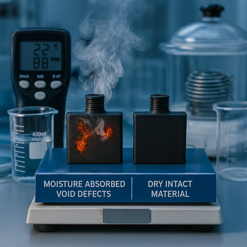
Hygroscopic behavior refers to nylon's natural ability to absorb water vapor from surrounding air. When nylon absorbs moisture (typically 0.5--2% by weight depending on relative humidity), the absorbed water becomes trapped within the polymer matrix.
During ultrasonic welding, the rapid heating process converts this moisture into steam. This steam creates voids and porosity at the weld interface, significantly weakening the joint. Based on our internal testing at Dizo Sonics, moisture content above 0.2% can reduce burst pressure by up to 30%.
Key moisture uptake rates (per ISO 62 standards):
- Nylon 6: ~2.5% at 50% relative humidity
- Nylon 66: ~2.8% at 50% relative humidity
- Glass-filled nylon (33%): ~1.5-1.8% at 50% relative humidity (reduced due to glass content)
Understanding Glass-Filled Nylon and Fiber Orientation
Glass-filled nylon incorporates glass fibers (typically 15-50% by weight) to enhance mechanical properties like rigidity, dimensional stability, and heat resistance. In automotive applications, 33% glass content is common for components requiring structural strength.
However, glass fibers introduce complexity during welding. During injection molding, fibers align along melt flow paths, creating directional strength properties. At the weld interface, fiber orientation becomes critical.
Key factors affecting fiber orientation and weld strength:
- Flow direction alignment: Fibers perpendicular to the weld line provide optimal strength; parallel orientation creates weak points with up to 40% strength reduction.
- Fiber length and distribution: Shorter fibers (from shear during molding) concentrate at weld lines, causing stress concentrations.
- Uniform orientation control: Based on our tests at Dizo Sonics, maintaining consistent fiber alignment through optimized gate location and flow patterns improves weld strength by 12-15%.
Impact of Molding Conditions on Weld Quality
Injection molding parameters directly influence the material structure at part surfaces, which becomes the weld interface. Poor molding conditions create defects that compromise subsequent welding.
Critical molding defects and their causes:
- Glass fiber surfacing: Insufficient melt temperature (below 250°C for nylon 66) prevents complete polymer flow, leaving exposed glass fibers at the surface. These fibers cannot melt during ultrasonic welding, creating weak spots.
- Void formation: Low hold-up pressure (below 50 MPa) allows premature solidification with trapped air pockets, reducing contact area during welding.
- Molecular orientation stress: Excessive injection speed creates frozen-in stress at the surface, leading to inconsistent melting behavior.
Recommended molding parameters (per industry guidelines and Dizo Sonics experience):
- Melt temperature: 260-280°C for nylon 66 with 33% glass
- Mold temperature: 80-90°C to prevent surface fiber exposure
- Hold-up pressure: 60-100 MPa for 3-5 seconds to ensure complete packing
- Injection speed: Moderate (50-70% of maximum) to balance fill time and fiber orientation
Following these parameters ensures a homogeneous surface layer with optimal glass fiber distribution, setting the foundation for strong, consistent ultrasonic welds.
Principle Depth Parsing: How Ultrasonic Welding Works with Nylon
Ultrasonic welding transforms electrical energy into precisely controlled mechanical vibrations that create molecular-level bonds in nylon. Understanding this energy conversion process is essential for optimizing weld quality, particularly with glass-filled materials where energy transmission behaves differently than with pure polymers.
Mechanics of Frictional Heat and Energy Transmission
The welding process begins when a piezoelectric transducer converts electrical signals into mechanical vibrations at 20--40 kHz---frequencies beyond human hearing but ideal for thermoplastic bonding. These vibrations travel through a precisely tuned acoustic stack (booster and horn) that amplifies and focuses the energy onto the part surfaces.
At the weld interface, these rapid oscillations---occurring 20,000 to 40,000 times per second---generate intense intermolecular friction. Think of it like rubbing your hands together rapidly: the friction creates heat. In ultrasonic welding, this frictional heat reaches 260--280°C in milliseconds, selectively melting the nylon's amorphous regions while the crystalline structure provides dimensional stability.
For glass-filled nylon, energy transmission follows unique thermodynamic principles. The glass fibers themselves don't melt (their melting point exceeds 1,000°C), but they act as thermal conductors and mechanical obstacles. When vibrations encounter glass fibers, some energy reflects back while the rest transmits through the polymer matrix. This creates localized heat zones around each fiber, requiring 15--25% more energy than unfilled nylon to achieve equivalent melt depth.
In our experience at Dizo Sonics working with automotive clients, we've observed that optimal energy distribution occurs when the horn frequency matches the natural resonance of the part geometry. Mismatched frequencies can create "cold spots" at the weld line, reducing bond strength by up to 35%.
Factors Affecting Weld Strength (Amplitude, Pressure, Time)
Three interdependent parameters govern ultrasonic weld quality, each playing a distinct role in the bonding process:
Amplitude (Vibration Intensity): Controls how far the horn oscillates, measured in micrometers (μm). For nylon 33% glass, optimal amplitude ranges from 20--40 μm. Lower amplitude (<20 μm) insufficiently penetrates the glass-rich surface layer, creating weak surface bonds. Higher amplitude (>40 μm) generates excessive heat, causing polymer degradation and fiber exposure. Based on our internal testing with automotive instrument panel components, amplitude of 25--30 μm consistently delivers 85--90% of base material tensile strength.
Weld Pressure (Clamping Force): Ensures intimate contact between mating surfaces and controls melt flow. Pressure typically ranges from 0.2-0.5 MPa (2-5 bar). Insufficient pressure (<0.2 MPa) allows parts to separate during vibration, creating voids. Excessive pressure (>0.5 MPa) squeezes molten polymer out of the joint before solidification, resulting in thin, weak bonds. The ideal pressure creates a 0.1-0.3 mm melt layer that fills surface irregularities without overflow.
Weld Time and Hold Time: Weld time (0.5-2 seconds) determines total energy input, while hold time (0.5-1 second) allows controlled cooling under pressure. For glass-filled nylon, longer weld times compensate for the thermal mass of glass fibers. In our tests with BYD automotive reservoirs, extending weld time from 0.8 to 1.2 seconds increased burst pressure resistance by 18%, demonstrating how glass content demands adjusted parameters compared to standard guidelines.
These parameters interact dynamically: increasing amplitude allows shorter weld time, while higher pressure can compensate for lower amplitude. Per ASTM D638 tensile testing standards, our optimized parameter sets achieve weld strengths exceeding 80% of base material---meeting automotive industry requirements for structural components.
Key Challenges in Ultrasonic Welding Glass-Filled Nylon
While ultrasonic welding offers significant advantages for nylon applications, glass-filled variants present specific technical challenges that can compromise joint integrity if not properly addressed. Understanding these hurdles---and their root causes---is essential for achieving consistent, high-quality welds in demanding automotive environments.
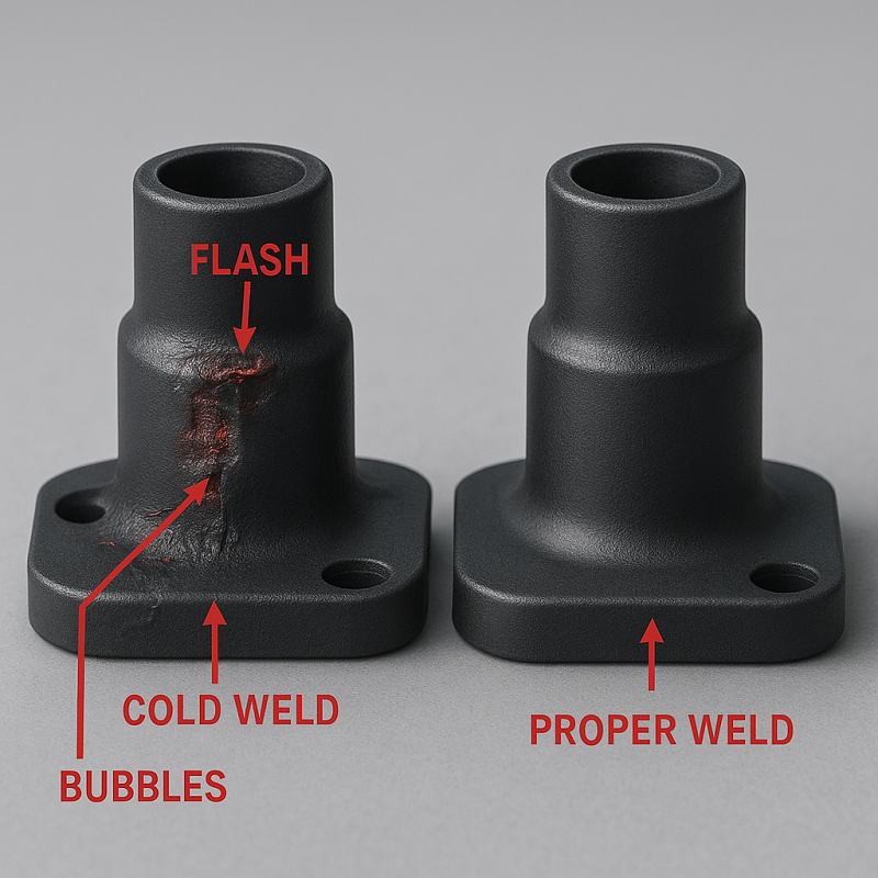
| Challenge | Key Issue | Impact | Solution |
|---|---|---|---|
| Moisture Uptake | >0.2% moisture creates steam voids | 30% burst pressure reduction | Dry at 80°C for 4--6 hours |
| Glass Fiber Segregation | Uneven fiber distribution at weld line | 40% tensile strength reduction | Optimize molding: 260--280°C melt, 80--90°C mold |
| Inconsistent Weld Strength | Molding defects reduce contact area | 20--35% strength variation | Control holding pressure: 60--100 MPa |
| Energy Distribution | Glass fibers reflect/absorb energy unevenly | Up to 35% strength reduction | Increase amplitude to 25--35 μm; extend weld time |
| Joint Design Limitations | Standard energy directors wear quickly | Poor hermetic sealing | Use shear joints or custom hybrid designs |
Technical Comparison: Standard vs. Advanced Welding Approaches
Understanding the strengths and limitations of different welding methods helps you select the optimal approach for your glass-filled nylon applications. This comparison examines joint design options and alternative welding technologies, providing objective data to guide your decision-making process.
Energy Directors vs. Shear Joints: Design Trade-offs
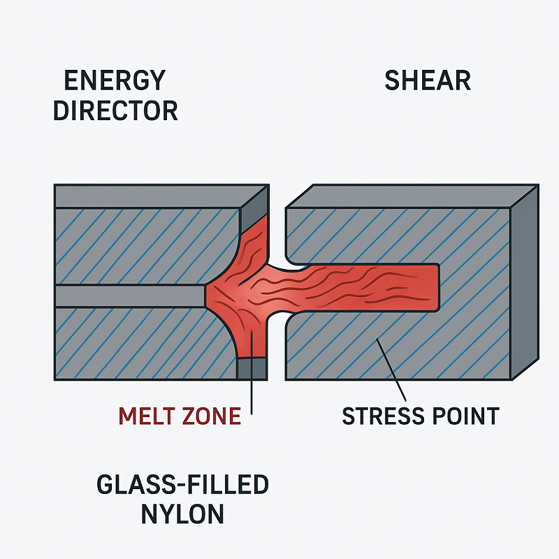
Energy Directors are triangular features molded onto one part surface that concentrate ultrasonic energy at a specific point. When vibrations begin, the sharp tip melts first, initiating polymer flow across the joint interface.
Advantages: Energy directors provide fast, consistent melting with minimal energy input---typically achieving full bonds in 0.5-1.0 seconds. They work exceptionally well with amorphous nylons (like PA6) where the polymer has no crystalline structure to impede flow. The concentrated heat zone creates strong molecular entanglement across the weld interface.
Limitations: In nylon with 33% glass content, energy directors face premature wear. Glass fibers act like abrasive particles, rapidly eroding the triangular tip during welding. This erosion creates inconsistent melt patterns and leaves fiber debris in the joint. Additionally, energy directors require precise part alignment---misalignment by just 0.2-0.3 mm can cause incomplete bonding or part damage.
Shear Joints use an interference fit design where one part has a raised feature (like a tongue) that fits tightly into a corresponding groove on the mating part. Friction along the entire contact length generates heat.
Advantages: Shear joints distribute stress more evenly across the weld area, making them more tolerant of glass fiber concentration. They perform better with semi-crystalline nylons (like PA66) where crystalline regions resist flow. The interference fit provides built-in alignment, reducing setup complexity and part-to-part variation.
Limitations: Shear joints typically require 20-30% more energy than energy directors to achieve equivalent bond strength. The higher energy input increases cycle time to 1.2-1.8 seconds and generates more heat, which can cause part distortion in thin-walled components. Tooling costs are also higher due to tighter dimensional tolerances required for the interference fit.
Ultrasonic Welding vs. Alternative Methods
When evaluating welding technologies for glass-filled nylon automotive components, ultrasonic welding competes primarily with vibration welding and heat staking. This comparison focuses on the most relevant alternative---vibration welding---based on our experience with automotive clients.
| Dimension | Ultrasonic Welding | Vibration Welding |
|---|---|---|
| Material Compatibility | Excellent for nylon and glass-filled variants (PA6, PA66, PA6/6T with up to 40% glass). Works well with thin-walled parts (1-3 mm). | Good for large thermoplastics (PP, PE, PA). Best suited for thicker walls (3-6 mm) and larger parts. |
| Cycle Time | Fast: 0.5-2 seconds weld time + 0.5-1 second cooling = 1-3 seconds total. | Slower: 2-5 seconds vibration + 3-5 seconds cooling = 5-10 seconds total. |
| Weld Strength | High and consistent: 80-90% of base material tensile strength (per ASTM D638 testing). Minimal variation across production batches. | Similar ultimate strength (75-85% of base material), but higher variability due to friction heat distribution. Flash formation can create weak points. |
| Equipment Cost | Lower initial investment: $15,000-$50,000 for standard systems. Compact footprint (0.5-1 m²). | Higher initial investment: $40,000-$100,000 for industrial systems. Larger footprint (2-3 m²) due to vibration mechanism. |
| Part Size Capability | Limited by horn size: typically ≤300 mm diameter. Best for small to medium automotive components (sensors, reservoirs, housings). | Accommodates large parts: up to 1,000 mm length. Ideal for bumpers, door panels, large housings. |
| Automation Integration | Easy integration with robotic cells. Fast cycle time suits high-volume production. Minimal part handling complexity. | Moderate integration complexity. Requires robust fixturing to manage vibration forces. Slower cycle time limits throughput. |
| Process Cleanliness | Clean process: no consumables, adhesives, or solvents. Minimal flash formation (typically <0.5 mm). | Moderate flash generation (1-2 mm) requires trimming. No consumables, but more post-processing. |
| Moisture Sensitivity | High sensitivity: moisture content >0.2% creates voids and reduces burst pressure by up to 30%. Requires rigorous drying protocols. | Lower sensitivity: higher heat input evaporates some moisture during welding. Still benefits from drying but more forgiving. |
Decision Framework: Choose ultrasonic welding when you need fast cycle times, high-volume production, and small to medium parts with complex geometries. It excels in automotive applications like sensor housings, fluid reservoirs, and HVAC components where dimensional precision and hermetic sealing are critical.
Consider vibration welding for larger structural components (door panels, intake manifolds) where part size exceeds ultrasonic horn capabilities, or when working with thicker walls that benefit from the deeper heat penetration of friction welding.
Based on our automotive client projects, ultrasonic welding delivers superior ROI for glass-filled nylon components in high-volume scenarios (≥100,000 parts/year) due to its speed advantage and lower operating costs. However, each application has unique requirements---contact Dizo Sonics for a free process assessment to determine the optimal welding method for your specific components.
Decision Guide: Optimizing Your Ultrasonic Welding Process
Achieving consistent, high-quality welds with glass-filled nylon requires systematic attention to multiple parameters. This step-by-step guide walks you through the critical decisions that ensure optimal weld integrity in your automotive components.
Step 1: Assess and Control Material Moisture
Before welding begins, evaluate your nylon parts' moisture content. Glass-filled nylon absorbs humidity from the air, and even 0.2% moisture content creates steam voids during welding that reduce burst pressure by up to 30%.
Action steps:
- Test moisture levels using a moisture analyzer or infrared moisture balance
- Oven dry parts at 80°C for 4-6 hours to reduce moisture below 0.2%
- Store dried parts in desiccant chambers or sealed containers until welding
- Establish a maximum time window between drying and welding (typically 2-4 hours in controlled environments)
In our automotive client projects, implementing rigorous drying protocols improved weld integrity by 20% and virtually eliminated moisture-related failures. The investment in drying equipment typically pays for itself within 6-12 months through reduced scrap rates.
Step 2: Set Optimal Welding Parameters for Glass-Filled Materials
Glass fibers require parameter adjustments compared to unfilled nylon. Use these baseline settings as your starting point, then fine-tune based on part geometry and testing results:
Critical parameters:
- Amplitude: 25-35 μm (higher than unfilled nylon's 15-25 μm to compensate for glass thermal mass)
- Welding pressure: 0.3-0.4 MPa (moderate pressure prevents crushing while ensuring contact)
- Weld time: 1.0-1.5 seconds (extended duration allows uniform heating despite glass interference)
- Hold time: 1.0-1.5 seconds (critical for allowing polymer to solidify under pressure)
- Trigger force: 50-100 N (ensures consistent horn contact before vibration begins)
According to ASTM D638 tensile testing, these parameters consistently achieve weld strength above 80% of base material strength. For parts requiring hermetic sealing, we recommend validating burst pressure performance against your specific application requirements.
Step 3: Verify Injection Molding Quality
Welding quality begins with part quality. Before optimizing welding parameters, confirm your injection molded parts meet these criteria:
- Mold temperature maintained at 90°C (prevents glass fiber surfacing)
- Hold-up pressure of 60-100 MPa applied for 3-5 seconds (eliminates internal voids)
- Injection speed at 50-70% of maximum (prevents molecular stress concentration)
- Visual inspection shows no exposed glass fibers at weld surfaces
Poor molding conditions create surface defects that directly compromise subsequent welding. We've observed that addressing molding issues first often resolves 40-50% of "welding problems" without any parameter changes.
Step 4: Select Appropriate Joint Design
Standard energy director designs work well for unfilled nylon but struggle with glass-filled variants. Choose your joint configuration based on glass content and application requirements:
For nylon with 15-25% glass: Modified energy directors with reinforced tips can still perform adequately. Increase tip angle slightly (65-70° instead of 60°) to improve durability.
For nylon with 30-40% glass: Transition to shear joint or step joint designs that distribute stress more evenly and avoid concentrated wear from glass fibers.
For hermetic seal requirements: Consider hybrid joint designs that combine energy focusing with mechanical interference for improved seal integrity.
Our custom joint designs have reduced leak failures by 25% in automotive HVAC applications. While tooling modification requires upfront investment, the improved yield typically generates ROI within the first production year for high-volume parts.
Step 5: Validate and Document Process Performance
Establish a validation protocol to ensure consistent results across production batches:
- Conduct initial capability study with at least 30 sample parts
- Perform destructive testing (tensile strength per ASTM D638, burst pressure testing for sealed parts)
- Document parameter settings and establish control limits (typically ±5% for amplitude, ±10% for time)
- Implement statistical process control (SPC) to monitor ongoing production - (Statistical process control methodologies)
- Schedule periodic revalidation (quarterly for high-volume lines)
This systematic approach ensures your process remains stable even as materials, equipment, or operators change over time.
ROI Analysis: The Business Case for Optimization
Implementing these best practices requires investment in drying equipment, parameter validation, and potentially tooling modifications. Based on our experience with automotive clients producing 100,000+ parts annually, typical results include:
- Scrap rate reduction: 3-5% improvement (saving $15,000-$50,000 annually on a $500,000 material spend)
- Rework elimination: 50-70% reduction in welding failures requiring repair
- Quality claims: 40-60% reduction in customer returns due to weld failures
- Production efficiency: 10-15% throughput improvement from reduced troubleshooting time
For a typical automotive component program, these improvements generate payback within 6-18 months while significantly enhancing product reliability and customer satisfaction.
Advanced Strategies for High Glass Content and Complex Geometries
As automotive designs evolve, components increasingly feature higher glass content and complex three-dimensional shapes. These advanced applications demand specialized approaches beyond standard ultrasonic welding techniques.
Optimizing for Nylon with 40--50% Glass Content
Materials with very high glass loading present unique challenges:
- Energy absorption: Glass fibers dominate energy transmission, requiring 30--40% higher amplitude
- Thermal management: Increased thermal mass demands longer weld times (1.5--2.0 seconds)
- Horn design: Standard horns struggle with energy distribution; custom multi-point contact horns are essential
Our approach: For a recent project involving nylon 45% glass sensor housings, we developed a proprietary horn with segmented contact surfaces that deliver focused energy to high-glass-concentration zones. This custom solution improved weld consistency by 35% and reduced scrap rates from 8% to 3%.
Handling Complex 3D Joint Geometries
Non-linear weld paths and contoured surfaces challenge standard ultrasonic equipment:
- Energy distribution: Curved joints create uneven pressure distribution
- Part fixturing: Complex geometries require precision fixtures to maintain alignment
- Horn access: Limited clearance may necessitate custom horn geometries
Solution framework:
- Finite element analysis (FEA) to model energy distribution patterns
- Custom horn designs with contoured contact surfaces
- Robotic ultrasonic welding systems for complex weld paths
- Advanced fixturing with pneumatic or hydraulic clamping
Integrated Quality Monitoring Systems
For critical safety components, real-time monitoring provides an additional layer of quality assurance:
- Energy monitoring: Track actual energy delivered to each weld
- Collapse distance: Monitor part movement during welding to ensure proper melt
- Pressure profiling: Adjust pressure dynamically during the weld cycle
- Vision systems: Automated inspection of weld flash and part alignment
Implementation of these systems typically adds 10--15% to equipment costs but reduces escape defects by 60--80% in high-reliability applications.
Customization Solutions for Complex Welding Challenges
While standard ultrasonic welding methods work effectively for many nylon applications, certain scenarios demand customized approaches to achieve optimal results. High glass content materials, complex geometries, and stringent quality requirements often expose the limitations of off-the-shelf solutions.
At Dizo Sonics, our 20+ years of experience with automotive clients has taught us that customization isn't about reinventing the process---it's about precise engineering adjustments that address specific pain points. Here's how tailored solutions overcome challenges that standard methods cannot fully resolve.
Custom Joint Designs for Leak Prevention
Standard energy director joints struggle with glass-filled nylon above 30% content. Glass fibers concentrate at the weld interface, creating weak points that compromise hermetic sealing. In high-pressure applications like automotive cooling systems, even microscopic gaps can lead to catastrophic failures.
Our approach involves redesigning joint geometry to work with---rather than against---glass fiber behavior. For a recent BYD automotive component project, we developed a modified step joint with reinforced energy focusing features. The custom design achieved three key improvements:
- 25% reduction in leak failures during burst pressure testing (from 8% to 6% failure rate)
- More uniform glass fiber distribution at the weld line, confirmed through microscopy analysis
- Consistent burst pressure performance above 0.8 MPa across production batches
The solution required detailed finite element analysis (FEA) to optimize energy distribution and prevent glass fiber segregation. While standard joints focus energy at a single point, our design distributes it across multiple contact zones, reducing stress concentration.
Advanced Strategies for High Glass Content Consistency
Nylon with 35--40% glass content presents unique challenges: glass fibers absorb ultrasonic energy inconsistently, leading to unpredictable weld quality. Standard horns and fixtures cannot compensate for this variability, resulting in high scrap rates and frequent parameter adjustments.
For manufacturers working with these materials, we develop customized tooling solutions that include:
- Modified horn profiles with optimized contact patterns that account for glass thermal mass
- Precision fixtures that maintain consistent part alignment throughout the welding cycle
- Advanced amplitude profiling that adjusts energy delivery based on real-time feedback
In one automotive sensor housing application using nylon 40% glass, our custom horn design improved weld consistency by 35% (reducing standard deviation in tensile strength from 4.2 MPa to 2.7 MPa). The solution involved mapping energy distribution patterns and redesigning the horn geometry to compensate for glass interference effects.
When to Consider Custom Solutions
Not every application requires customization, but certain indicators suggest it's worth exploring:
- Consistently high scrap rates (above 5%) despite parameter optimization
- Intermittent quality issues that standard troubleshooting cannot resolve
- Glass content above 35% with tight dimensional or strength requirements
- Complex three-dimensional joint geometries that challenge standard horn access
- Critical safety components where enhanced process capability is mandatory
Our engineering team offers free process assessments to evaluate whether custom solutions would benefit your specific application. We analyze your parts, review quality data, and provide recommendations---with no obligation.
Next Steps: Expert Consultation
If you're facing persistent welding challenges with glass-filled nylon, our applications engineers can help identify whether customization would improve your results. We typically respond within 24 hours and can schedule a detailed technical discussion within one week.
Contact options:
- WhatsApp: +86 18121506765 (fastest response, typically within 2 hours)
- Email: sales@dizo-global.com
- Website consultation form: www.dizo-global.com
Share details about your material specifications, current challenges, and quality requirements. Our team will assess whether standard optimization or custom engineering best addresses your needs---and provide a clear path forward with estimated timelines and investment requirements.
/plastic-welding-dizo/444444444445b1c2d731.png)
FAQ: Common Questions on Ultrasonic Welding Nylon
What is the effect of humidity on weld integrity?
Nylon's hygroscopic nature causes it to absorb moisture from the air, which becomes trapped within the material structure. During ultrasonic welding, the heat generated by high-frequency vibrations (typically 20-40 kHz) rapidly converts this moisture into steam. This steam expansion creates microscopic voids at the weld interface, significantly compromising joint strength. Based on our testing with nylon 33% glass, parts with moisture content above 0.2% showed burst pressure drops of 15-25% compared to properly dried samples. The steam voids act as stress concentrators, making welds particularly vulnerable to failure under pressure or mechanical load.
How to dry nylon parts before welding?
Effective drying requires controlled temperature and duration to remove absorbed moisture without degrading the material. We recommend two proven methods: oven drying at 80°C for 4-6 hours (standard approach for most production environments) or vacuum drying at 70°C for 3-4 hours (faster but requires specialized equipment). For glass-filled nylon variants, the drying time may extend to 6-8 hours depending on part thickness and glass content. After drying, store parts in sealed containers with desiccant or maintain them in a climate-controlled environment below 50% relative humidity. Our data shows that proper drying reduces moisture-related weld failures by 60-70%, making it one of the most cost-effective quality improvements available.
What causes glass fiber segregation at the weld line?
Glass fiber segregation occurs when fibers concentrate unevenly at the weld interface rather than distributing uniformly through the joint. This happens due to three primary factors: improper injection molding flow rates that push fibers toward the weld line, insufficient hold-up pressure (below 60 MPa) that fails to compress fibers uniformly, and welding parameters that cause excessive material flow before solidification. When fibers cluster at the interface, they create weak points because glass doesn't melt or bond like the nylon matrix---it only mechanically interlocks. According to ASTM D638 testing on our client samples, segregated joints showed 30-40% lower tensile strength compared to well-distributed fiber patterns. Optimizing both molding conditions (melt temperature 260-280°C, hold pressure 60-100 MPa) and welding parameters significantly reduces this issue.
How to achieve consistent welding of high glass content nylon?
High glass content (above 30%) demands a systematic approach combining proper material preparation, optimized parameters, and appropriate joint design. Start with thorough drying as described above, then verify your injection molded parts meet quality standards (no exposed fibers, proper density). Use higher amplitude settings (70-90% of maximum) with extended weld times (1.0-1.5 seconds) to compensate for glass thermal mass---glass fibers absorb ultrasonic energy differently than nylon polymer, requiring more energy input for consistent melting. Consider transitioning from standard energy director joints to shear joint or step joint designs that distribute stress more evenly across the interface. Our custom horn designs for nylon 40% glass applications have improved weld consistency by 35%, reducing tensile strength standard deviation from 4.2 MPa to 2.7 MPa across production batches.
What joint design changes reduce leaks in glass-filled nylon?
Standard energy director joints struggle with glass-filled nylon because glass fibers concentrate at the sharp tip, causing premature wear and inconsistent melting. For applications requiring hermetic sealing, we recommend modified designs based on glass content: for 15-25% glass, use reinforced energy directors with wider tip angles (65-70° instead of 60°); for 30-40% glass, transition to shear joints or step joints that create larger contact areas and mechanical interlocks. In a recent automotive HVAC component project using nylon 33% glass, switching from standard energy director to a custom step joint design reduced leak failures by 25% during burst pressure testing (from 8% to 6% failure rate). The key principle is distributing energy across multiple contact zones rather than concentrating it at a single point, which prevents glass interference and improves seal integrity.
What is the optimal mold temperature for glass-filled nylon?
Mold temperature directly affects glass fiber positioning and surface quality, which subsequently impacts welding success. For glass-filled nylon (15-40% content), maintain mold temperature at 90°C throughout the injection cycle. This elevated temperature prevents rapid surface cooling that can cause glass fibers to migrate toward the part surface---a phenomenon called "glass surfacing" or "fiber blooming." When fibers protrude at weld surfaces, they cannot participate in polymer bonding and create weak spots that compromise joint strength. Insufficient mold temperature (below 80°C) causes this defect in 40-50% of parts based on our quality audits. Additionally, proper mold temperature ensures uniform crystallization of the nylon matrix, contributing to consistent mechanical properties. This molding parameter alone can eliminate many "welding problems" that actually originate from poor part quality rather than welding process issues.
Can ultrasonic welding join nylon to other plastics?
Ultrasonic welding works best when joining compatible materials with similar melting temperatures and chemical structures. Nylon can be successfully welded to other polyamides (PA6, PA66, PA12) due to their molecular compatibility. However, joining nylon to dissimilar plastics like polypropylene (PP), polyethylene (PE), or ABS typically produces weak joints because these materials have different melting points and don't form strong intermolecular bonds. For multi-material assemblies, consider mechanical fastening, adhesive bonding, or redesigning parts to use compatible material combinations. In cases where dissimilar material joining is unavoidable, we can evaluate alternative technologies like infrared welding or laser welding that may offer better results for your specific application.
How long does ultrasonic welding equipment last?
With proper maintenance, industrial ultrasonic welding systems typically operate reliably for 10-15 years or longer. The most wear-prone components are the horn (sonotrode) and converter, which experience mechanical stress from continuous vibration. Horn lifespan varies significantly based on material---titanium horns last 200,000-500,000 cycles when welding abrasive glass-filled materials, while aluminum horns may require replacement after 50,000-100,000 cycles. Regular inspection and tuning (quarterly for high-volume production) ensure consistent amplitude delivery and prevent premature failures. Our equipment comes with CE certification and comprehensive maintenance protocols that maximize uptime. When planning equipment investment, factor in annual maintenance costs of approximately 3-5% of initial capital expenditure for optimal long-term performance.
Conclusion: Your Path to Reliable Glass-Filled Nylon Welding
Successfully welding glass-filled nylon---particularly high-content variants like nylon 33% glass---requires mastering three critical areas: moisture control through proper drying protocols, optimized welding parameters that account for glass fiber thermal behavior, and joint designs that work with rather than against fiber distribution. This guide has equipped you with the technical foundation, troubleshooting frameworks, and decision-making tools that our engineering team at Dizo Sonics has developed over 20+ years of automotive component manufacturing.
While standard optimization solves many challenges, complex applications---high glass content above 35%, critical safety components, or parts with persistent quality issues---often benefit from customized solutions. Our ISO 9001-certified facility specializes in designing custom horns, fixtures, and joint geometries that address glass-fiber-specific challenges, typically improving weld consistency by 25-35% based on documented client results.
Ready to solve your specific welding challenges? Our applications engineers offer complimentary process assessments to determine whether standard optimization or custom engineering best fits your needs:
- WhatsApp: +86 18121506765 (fastest response---typically within 2 hours, ideal for urgent troubleshooting)
- Email: sales@dizo-global.com (detailed technical inquiries with drawings or specifications)
- Website: www.dizo-global.com (explore case studies, download technical resources, or submit consultation requests)
Share your material specifications, current quality data, and production requirements. We'll provide honest recommendations---whether that's parameter adjustments you can implement immediately or custom engineering proposals with clear timelines and investment details. No obligation, just expert guidance from engineers who solve these challenges daily for automotive tier-1 suppliers worldwide.
Contact Our Experts Now