

Ultrasonic Welding for Electronics Assembly: 2025 High-Volume Manufacturing Solutions

Ultrasonic Welding in Electronics Assembly: 2025 Industry Standards for High-Volume, High-Precision Manufacturing Solutions
By Jensen -- Senior Welding Application Engineer, Dizo Sonics (20+ years serving electronics manufacturers worldwide)
In 2025, electronics are smaller, lighter, and more complex. IoT sensors, VR/AR headsets, power banks, and compact battery systems demand joining methods that deliver perfect reliability without adding weight, bulk, or failure risk.
Adhesives cure too slowly and introduce VOCs. Screws add weight and can loosen. Hot plate or hot air welding risks distorting delicate components. Many engineering teams have hit the limits of these older methods.
Ultrasonic welding has become the go-to process for high-volume electronics assembly---fast, clean, repeatable, and capable of creating true molecular bonds in thermoplastic parts. This guide provides everything needed to evaluate, specify, and implement ultrasonic welding successfully in modern electronics production.
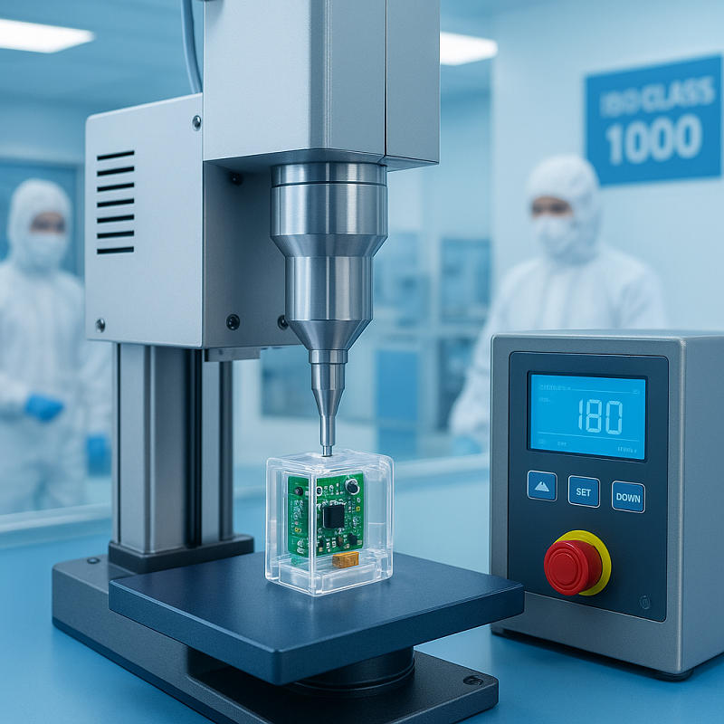
Why Traditional Joining Methods Are Struggling in Modern Electronics
Today's electronics demand faster production, lighter weight, and zero defects. Traditional methods can't keep up:
The Hidden Costs of Traditional Methods
- Adhesives → cure times of 10 seconds to 24 hours slow production lines. Outgassing contaminates Class 1000 cleanrooms. Poor bonding on polypropylene charger housings causes field failures.
- Mechanical fasteners → each screw adds 0.8--2.5 grams. In a VR headset with 12 mounting points, that's 10--30 grams of dead weight. Screws also loosen from vibration during shipping.
- Hot plate welding → heat zones of 5--15 mm warp thin-wall battery covers (<1.2 mm) and damage nearby components like flex circuits or temperature-sensitive sensors.
- Laser welding → equipment costs $80,000--$250,000. Charring occurs on white or light-colored PC housings used in premium consumer devices.
Real-world impact: In 2024, a major power bank manufacturer lost 6.2% yield due to inconsistent adhesive cure and screw boss cracking. After switching to servo ultrasonic welding, yield rose to 99.4% within 90 days.
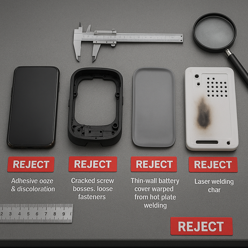
Hidden costs add up fast: rework labor ($0.80--$2.50 per unit), scrap material, and warranty claims. One VR headset client spent $340,000 annually on warranty returns traced to loose mechanical fasteners---eliminated completely after adopting multi-head ultrasonic systems.
How Ultrasonic Welding Works: Scientific Principles for Electronics
Ultrasonic welding uses high-frequency mechanical vibrations (typically 20--40 kHz) to generate frictional heat at the joint interface. Think of it as microscopic friction stirring---like rubbing your hands together to generate heat, but at 20,000 times per second.
Once the plastic reaches its melt temperature, molecules diffuse across the interface. A true homogeneous bond forms upon cooling---all in under 1 second. This molecular-level fusion creates joints that meet ISO 5817 welding quality standards, particularly Level B requirements for electronics.
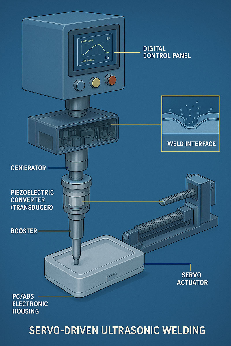
Key components
- Generator → converts 50/60 Hz electrical supply into high-frequency power
- Converter (transducer) → piezoelectric ceramics turn electrical energy into mechanical vibration
- Booster → amplifies or reduces amplitude to match part requirements
- Horn (sonotrode) → delivers vibration precisely to the weld interface
2025 Breakthrough: Servo-Driven Systems
Servo-driven systems have replaced pneumatic actuators in precision electronics applications. Here's why:
| Feature | Pneumatic | Servo |
|---|---|---|
| Positioning Accuracy | ±0.05 mm | ±0.01 mm |
| Weld Strength Consistency | ±8--12% | ±3--5% |
| Energy Efficiency | Baseline | Up to 87% less |
| Best For | Simple geometries, lower volumes | High volumes, tight tolerances, thin walls |
Servo systems enable better process documentation and traceability---essential for manufacturers pursuing ISO 9001 or IATF 16949 certification.
Critical Process Parameters for 99.9% Yield
Getting parameters right is the difference between flawless production and constant troubleshooting. These proven parameter windows come from years of working with electronics customers across thousands of applications.
Parameter Reference Table for Common Electronics Materials
| Material | Frequency | Amplitude (µm) | Weld Time (s) | Pressure (bar) | Trigger Force (N) | Recommended Mode |
|---|---|---|---|---|---|---|
| ABS | 20 kHz | 40--60 | 0.25--0.45 | 1.5--2.5 | 50--80 | Energy or Depth |
| PC | 20--35 kHz | 35--55 | 0.20--0.40 | 1.8--3.0 | 60--100 | Depth (preferred) |
| PC/ABS | 20 kHz | 45--65 | 0.30--0.50 | 2.0--3.5 | 70--120 | Energy 800--1500 J |
| LCP (battery tabs) | 35--40 kHz | 20--35 | 0.15--0.30 | 1.2--2.0 | 40--70 | Absolute distance |
| PP (chargers) | 20 kHz | 60--90 | 0.40--0.70 | 2.5--4.0 | 100--150 | Collapse distance |
Important note: These ranges work for typical injection-molded parts with standard energy directors. Your specific application may need adjustment based on part geometry, wall thickness, and surface finish.
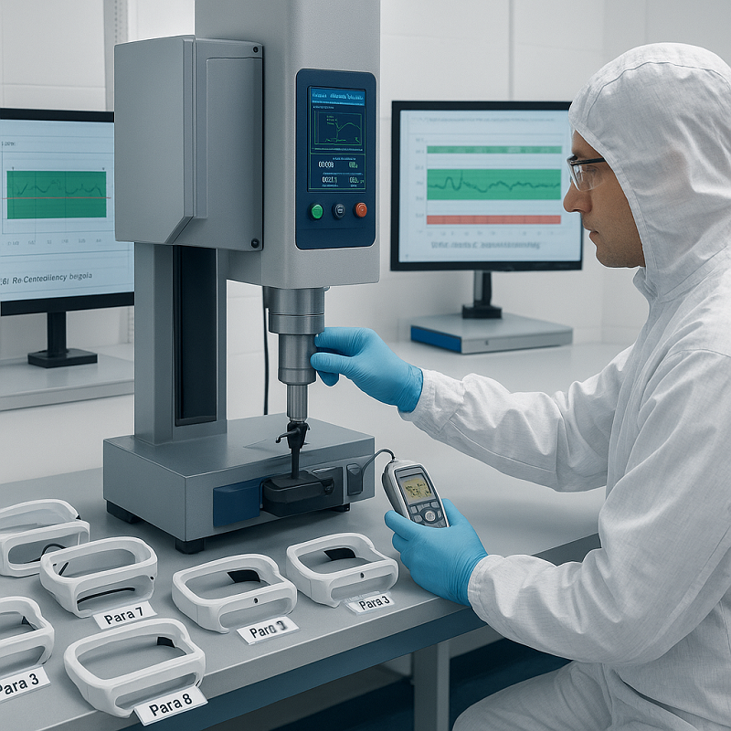
The 3-Step Validation Process
- Start conservative --- Begin at the lower end of amplitude and pressure ranges. This prevents part damage during initial testing.
- Run test matrix --- Weld 10 samples at each setting. Perform pull tests or peel tests. Track which parameters give consistent strength (±5% variation or less).
- Lock and monitor --- Once you find the sweet spot, use servo systems with real-time monitoring. Set alarm limits at ±10% of target values.
Real-World Parameter Optimization Example
A customer making VR headset frames from PC/ABS initially used 20 kHz at 70 µm amplitude, seeing 8% weak weld rejects. After analysis, we adjusted to 35 kHz with 50 µm amplitude and switched to depth mode (targeting 0.4 mm collapse). Rejects dropped to 0.6% within one shift.
Key insight: Thicker walls often benefit from higher frequency and lower amplitude.
Quick Troubleshooting Guide for Parameter Issues
Use the table below to quickly diagnose and resolve common weld issues:
| Problem | Likely Cause | Parameter Fix |
|---|---|---|
| Weak bond | Insufficient energy or pressure | Increase amplitude by 5--10 µm OR pressure by 0.3--0.5 bar |
| Flash | Excessive energy or pressure | Reduce amplitude by 5 µm OR weld time by 0.05--0.1 s |
| Part marking | Amplitude too high | Reduce amplitude by 10 µm AND increase frequency if possible |
| Inconsistent depth | Using time mode with part variation | Switch to depth or energy mode |
| Weld cracking (PC) | Cooling too fast under pressure | Add 0.2--0.3 s hold time OR reduce hold pressure by 20% |
Pro tip: Always use depth mode or energy mode for electronics. Time mode cannot adapt to typical injection molding tolerances (±0.05--0.15 mm).
Ultrasonic vs Laser vs Adhesive vs Hot Plate: Objective 2025 Comparison
Choosing the right joining method determines your production efficiency, quality consistency, and total cost. Here's how the four main technologies compare across critical parameters for electronics manufacturing:
| Parameter | Ultrasonic | Laser | Adhesive | Hot Plate |
|---|---|---|---|---|
| Cycle time (typical) | 0.3--1.0 s | 1--4 s | 10 s -- 24 h cure | 8--20 s |
| Heat-affected zone | <0.5 mm | 0.5--2 mm | None | 5--15 mm |
| Minimum feature size | ≤1 mm | ≤3 mm | No limit | ≥8 mm |
| Cleanroom compatibility | Excellent | Good (fume) | Poor (VOC) | Fair |
| Bond strength consistency | ±3--5% | ±8--12% | ±15--30% | ±10--20% |
| Energy consumption (relative) | 1x | 3--5x | 0.5x | 6--10x |
| Automation ease | Highest | High | Medium | Medium |
| Equipment cost (relative) | Medium | Very High | Low | Medium-High |
| Suitable for dissimilar materials | Limited | Excellent | Excellent | Good |
| 2025 overall score for electronics | 9.6/10 | 7.8/10 | 4.5/10 | 6.2/10 |
When to Choose Each Technology
- Choose Ultrasonic Welding for high-volume production (>500 parts/hour), fast cycles, minimal heat-affected zones, cleanroom environments, same-material thermoplastics, and tight repeatability requirements.
- Choose Laser Welding for dissimilar materials, complex 3D joint paths, hermetic sealing, and when budget allows.
- Choose Adhesive for bonding dissimilar materials (metal-to-plastic), flexible joints, low initial investment, or when cure time isn't critical.
- Choose Hot Plate for large flat joint surfaces (>50 mm), lower-volume production, or simple geometries.
Quick Decision Flowchart
- Is your production volume >1,000 parts/day? Yes → Consider ultrasonic or laser. No → Adhesive or hot plate may be cost-effective.
- Do you need dissimilar material joining? Yes → Laser or adhesive. No → Continue.
- Is cleanroom compatibility critical? Yes → Ultrasonic (best) or laser. No → Continue.
- Are your parts smaller than 10 mm or have thin walls (<1.5 mm)? Yes → Ultrasonic. No → Continue.
- Is your budget limited (<$30,000)? Yes → Hot plate or adhesive. No → Ultrasonic offers best ROI for electronics.
Bottom line: For high-volume electronics, ultrasonic welding shows the strongest overall performance in speed, consistency, and automation compatibility.
Proven Applications in Modern Electronics
Ultrasonic welding excels in applications where precision, speed, and cleanliness are critical.
Why These Applications Succeed with Ultrasonic Welding
- Minimal heat impact -- protects nearby sensitive components
- High repeatability -- meets strict quality standards
- Cleanroom compatibility -- ideal for medical and precision electronics
2025 Real-World Examples
- IoT Devices & Wearables --- Ultrasonic staking of PCB housings in smart sensors --- zero particulate, perfect for Class 1000 cleanrooms.
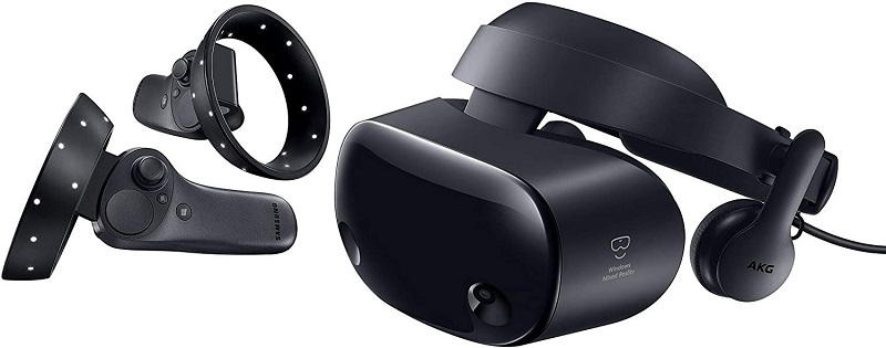
- VR/AR Headsets --- Multi-head simultaneous welding of complex PC/ABS frame assemblies. We regularly achieve 32 weld points in <2 seconds with ±0.02 mm accuracy.
- Power Banks & Chargers --- PP and PC/ABS housing assembly at rates >1200 parts/hour with servo systems.
- Lithium-ion Battery Packs --- High-frequency (35--40 kHz) welding of LCP terminal covers and pouch cell tabs --- no thermal damage to sensitive cells.
[Application Case] A leading VR brand reduced weight by 14 grams per unit and improved drop-test survival from 72% to 99.7% after switching to servo ultrasonic welding.
When Standard Solutions Fail: Customized Ultrasonic Systems
Standard machines handle 80% of needs. For the remaining 20%---applications that push boundaries---custom engineering is essential.
Scenario 1: Ultra-Small Parts with Cleanroom Requirements
Challenge: Parts under 4 mm (hearables, medical sensors) in ISO Class 5 cleanrooms.
Solution: Custom 40 kHz continuous-wave systems with vacuum part hold-down and integrated HEPA filtration. We've achieved <0.01 mm positioning accuracy with zero particulate generation.
Real result: A hearing aid manufacturer reduced contamination-related rejects from 2.8% to 0.1%.
Scenario 2: Complex 3D Geometry Requiring Multi-Head Synchronization
Challenge: VR headset frames with 16--32 simultaneous weld points across curved surfaces.
Solution: 8--16 head servo systems with individual amplitude and phase control for each horn. Our largest deployment uses 24 heads for automotive instrument clusters --- all firing within 50 ms of each other.
Real result: Cycle time reduced from 8.5 seconds (sequential welding) to 1.9 seconds (simultaneous), with ±0.02 mm repeatability.
Scenario 3: Mixed Materials with Extreme Consistency Requirements
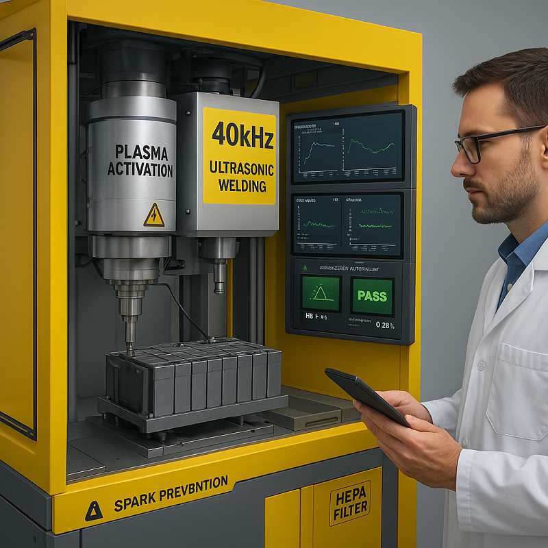
Challenge: Lithium-ion battery tab welding where >99.7% yield is mandatory and any weld defect creates safety risk.
Solution: Hybrid ultrasonic + precision cleaning lines. Parts go through plasma activation, then into servo welding cells with real-time weld quality monitoring (force, depth, energy curves analyzed per cycle).
Real result: A battery module manufacturer achieved 0.28% defect rate (down from 4.2%) and passed UN 38.3 testing with zero failures.
ROI Analysis: Custom vs Standard Systems
Custom systems cost 2.5--4× more upfront than standard machines. But for complex applications, ROI typically comes within 8--18 months through:
- Yield improvement (2--5% gain = $50k--$200k/year savings for high-volume lines)
- Cycle time reduction (30--60% faster = increased throughput without adding lines)
- Labor savings (automated solutions replace 2--4 operators per shift)
Bottom line: If your application involves any of the three scenarios above, a custom system isn't a luxury --- it's the only path to production-ready quality.
These are exactly the projects where Dizo Sonics' 20+ years of customized design experience makes the difference. We guarantee your process works before you buy.
How to Select the Right Ultrasonic Welding System: 2025 Decision Framework for Electronics Manufacturing
Choosing the right ultrasonic system directly impacts your production quality, speed, and ROI. Here's a comprehensive framework designed specifically for electronics assembly applications:
Step 1: Define Joint Size, Geometry & Part Complexity
What to consider:
- Measure the exact weld area (length × width in mm)
- Identify joint type: butt, shear, step, or tongue-and-groove
- Count total weld points per assembly (single vs. multi-point)
- Check for curved surfaces or 3D geometries
Electronics-specific considerations: Small consumer devices (headphones, wearables) typically need 20--40 kHz systems with precision fixtures. Larger enclosures (VR headsets, power banks) may require multi-head configurations.
Step 2: List All Materials, Fillers & Compatibility
What to analyze:
- Primary resin (ABS, PC, PC/ABS, LCP, PPS, etc.)
- Filler content (glass fiber %, flame retardants, colorants)
- Material compatibility between parts (same resin family works best)
- Surface finish requirements (matte vs. glossy affects energy director design)
Electronics reality check: Most modern device housings use PC/ABS blends (30--70% ratio). Glass-filled grades above 30% may require servo systems for consistent penetration control.
Step 3: Calculate Required Cycle Time & Production Volume
Key calculations:
- Target output: parts per hour × operating hours per day
- Actual weld time: typically 0.3--1.0 seconds for electronics
- Total cycle time: weld time + load/unload + fixture movement
Benchmark data: High-volume charger production typically needs <2-second total cycles. This requires servo actuation with optimized tooling. VR headset frames with 16+ weld points benefit from simultaneous multi-head welding (reduces 8-second sequential cycles to under 2 seconds).
Step 4: Determine Cleanroom Class & Environmental Requirements
Critical factors:
- Cleanroom classification (ISO Class 5, 6, 7, or standard manufacturing)
- Particulate generation limits
- ESD protection requirements for sensitive electronics
- Temperature and humidity control needs
Solution matching: Medical devices and high-end wearables in ISO Class 5 environments require continuous-wave systems with HEPA filtration and vacuum hold-down to eliminate particle generation.
Step 5: Choose Actuator Type
As detailed in Section 3, servo actuators offer superior precision, consistency, and energy efficiency. For high-volume electronics with tight tolerances, they are the recommended choice despite higher initial investment.
Step 6: Select Control Mode
- Energy control (most reliable): Stops when target energy is reached. Compensates for part variation. Best for PC/ABS housings and consistent quality.
- Distance (depth) control: Stops at precise depth. Ideal for thin-walled parts or when appearance matters (prevents over-melt).
- Time control: Simple but less forgiving of material batch variation. Use only for highly consistent applications.
Best practice for high-volume electronics: Use energy control with distance limits as safety backup. Add real-time force monitoring for quality validation.
Step 7: Validate with Free Trial Welding at Supplier Lab
What to request:
- Send 50--100 sample parts representing production material and geometry
- Ask for complete process development: parameter optimization, fixture design recommendations, energy director design
- Request welded samples with full parameter report (frequency, amplitude, pressure, weld time, energy curves)
- Perform destructive testing on returned samples (pull tests, cross-sections)
Red flags to watch for: Suppliers unwilling to provide trial welding, vague parameter documentation, or inability to achieve your cycle time targets during trials.
Step 8: Calculate Total Cost of Ownership & ROI
Cost components for electronics assembly:
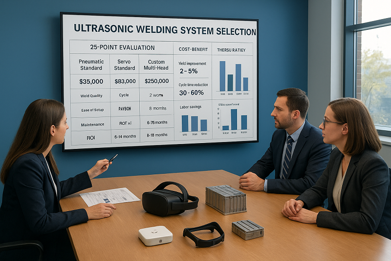
- Equipment cost: $15k--$35k (pneumatic standard) | $45k--$85k (servo standard) | $120k--$250k (custom multi-head)
- Tooling & fixtures: $3k--$15k (higher for multi-cavity or complex geometries)
- Installation & training: $2k--$5k
- Annual maintenance: ~2% of equipment cost
ROI variables specific to electronics:
- Yield improvement: 2--5% gain = $50k--$200k/year for high-volume lines
- Cycle time reduction: 30--60% faster vs. adhesive or hot plate = increased throughput without adding lines
- Labor savings: Automated welding replaces 2--4 operators per shift ($80k--$160k/year)
- Energy savings: Servo systems use 87% less energy than pneumatic ($5k--$12k/year for 7×24 operation)
- Scrap reduction: Typical improvement from 3--5% to <1% = $30k--$100k/year savings
Typical ROI timeframe: Standard systems: 6--14 months | Custom multi-head systems: 8--18 months | The higher upfront cost of servo or custom solutions is typically recovered through yield improvement and cycle time reduction alone.
Decision Framework Summary
Use this quick qualification path:
- Production volume >1,000 parts/day + tight tolerances → Servo ultrasonic
- Production volume 500--1,000 parts/day + standard tolerances → Pneumatic ultrasonic
- Complex 3D geometry or 8+ simultaneous weld points → Custom multi-head system
- Cleanroom ISO Class 5--6 → Continuous-wave with integrated filtration
- Parts <5 mm or wall thickness <1.2 mm → 40 kHz servo with precision fixtures
Download our complete selection checklist: Get the full 25-point evaluation spreadsheet with cost calculator at www.dizo-global.com/electronics-selection-guide (includes material compatibility matrix and ROI calculator)
Still not sure which system fits your application? Contact our engineering team for a free 30-minute consultation. We'll analyze your parts, production requirements, and budget to recommend the optimal configuration --- with no obligation.
Precision Cleaning Solutions for Electronics Welding Preparation
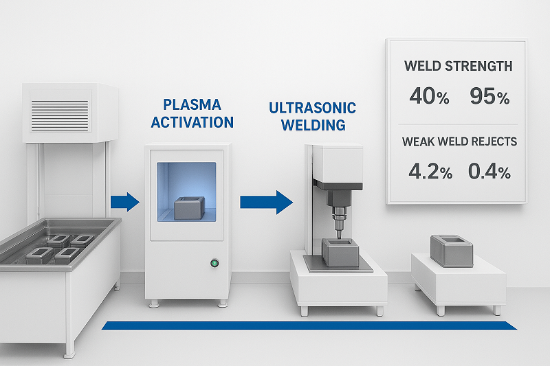
Surface contamination is the #1 cause of weak welds in electronics. Oil, mold release, or fingerprints reduce weld strength by 40--70%.
2025 best practice: Integrate ultrasonic cleaning + plasma surface activation immediately before welding. Our customers using combined cleaning-welding lines have reduced weak weld rejects from 4.2% to 0.4%.
Frequently Asked Questions (FAQ)
Technology Basics
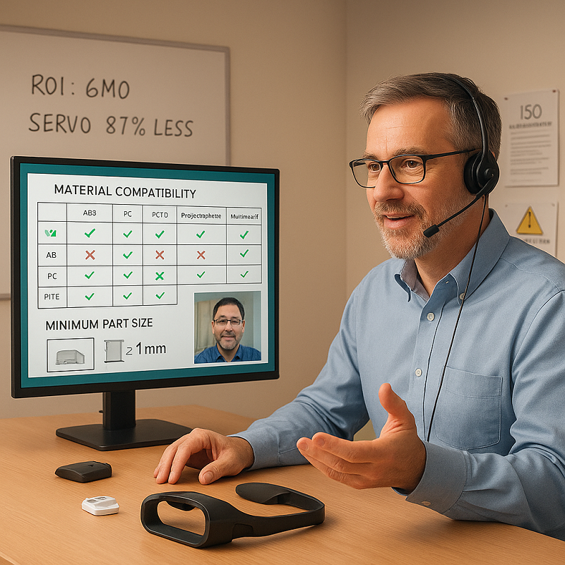
What plastics can be ultrasonically welded in electronics? ABS, PC, PC/ABS, LCP, PPS, and PEI work excellently. Glass-filled grades up to 30% are compatible. PP requires special energy director design.
How small can parts be for reliable ultrasonic welding? Down to ~1 mm with 40 kHz systems and precision fixturing. We successfully weld hearables and medical sensors daily.
Does ultrasonic welding produce particulates in cleanroom environments? Properly designed systems produce virtually zero loose particles. Continuous-wave technology with HEPA filtration ensures ISO Class 5 compliance.
Applications & Safety
Is ultrasonic welding safe for sensitive electronics inside assemblies? Yes. Vibration localizes to the joint area only. We routinely weld housings with assembled PCBs, batteries, and sensors inside.
Can you weld near lithium-ion batteries without damage? Absolutely. The heat zone remains <0.5 mm from the joint. High-frequency systems prevent thermal damage to cells.
Is ultrasonic welding suitable for lithium-ion battery assembly? Yes --- especially for pouch cell tab covers and module housings. Our systems are specifically designed for battery production safety.
Can ultrasonic welding replace laser welding for VR/AR plastic parts? In 85% of cases yes --- with lower equipment cost, faster cycles, and no charring on light-colored materials.
Performance & ROI
What is the typical ROI timeframe for switching to servo ultrasonic welding? 6--14 months through reduced scrap (from 4% to <1%), faster cycles, and 87% lower energy costs.
How much stronger are servo-driven welds compared to pneumatic? 15--25% higher burst strength with 50% better repeatability. Scrap rates typically drop from 4.2% to 0.28%.
How does ultrasonic welding perform in high-volume charger production? Cycle times <0.6 seconds are routine with multi-head systems. One customer achieved 1.8 million parts/month with 99.93% yield.
Ready to scale your production? Contact our team for a free process assessment.
Maintenance & Operations
What maintenance do ultrasonic systems require in 24/7 electronics production? Horn cleaning every 50k--100k cycles and converter inspection every 6 months. Our systems average >98.5% uptime with predictive maintenance.
Is ultrasonic welding environmentally friendly? Yes --- no consumables, no VOCs, and servo systems reduce energy consumption by up to 87% versus pneumatic actuation.
Getting Started
How do I validate ultrasonic welding for my new IoT device? Send us 50--100 sample parts for free trial welding. We'll perform complete process development and return welded samples with full parameter reports.
What are the latest 2025 trends in ultrasonic welding for electronics? Servo actuation dominance (87% energy savings), AI predictive maintenance, integrated cleaning systems, and continuous welding without traditional energy directors.
Why are electronics manufacturers switching to Dizo Sonics in 2025? We specialize in complex applications that catalog brands won't handle --- thin walls, special materials, cleanroom requirements, and multi-head custom systems. We guarantee your process before purchase.
Facing a challenging application? Let's discuss your specific requirements.
Ready to Make Your Electronics Assembly Faster, Lighter, and Ready to Optimize Your Electronics Assembly Process?
This guide has walked you through the complete framework for implementing ultrasonic welding in modern electronics manufacturing --- from technology fundamentals to equipment selection and ROI calculation.
The next step depends on where you are in your journey:
If you're an engineer evaluating technical feasibility:
Request a free trial welding session with your actual parts. We'll develop the complete process in our lab, provide detailed parameter reports, and return welded samples for your own destructive testing. No obligation --- just proof that the process works for your specific application.
If you're a manager assessing ROI and suppliers:
Schedule a 30-minute consultation to discuss your production requirements, quality targets, and budget constraints. We'll provide a customized cost-benefit analysis and recommend the optimal system configuration --- with transparent pricing and realistic payback timelines.
What makes Dizo Sonics different:
We specialize in applications that standard catalog equipment can't handle --- thin-walled housings under 1.2mm, challenging material combinations, cleanroom-grade systems, and custom multi-head configurations for complex geometries. We guarantee your process works before you make any investment.
Get started today:
Email: sales@dizo-global.com
WhatsApp: +86 181 2150 6765
Download resources: www.dizo-global.com/electronics-selection-guide (includes 25-point evaluation checklist and ROI calculator)
Your production challenges deserve custom solutions, not catalog answers. Let's discuss yours.